Overview
This will explain how to read the Hand and Mini IO pinouts from the manuals and how to access them from your WinCAPS project.
Note:
The examples shown below show the pinouts for the RC8(A) controller IO. However, the same concept can be applied to other versions of the controller using the correct pinout diagram from the manuals.
First Step: How to read the pinout diagrams and determine which wire is for what.
This is the hand IO diagram for RC8 in the manuals. The "reinforced" wire colors are special order and extremely rare so you will most likely be using the "standard" column. The hand IO comes in twisted pair colors, so you can have some duplicate color wires but not duplicate pairs of colors.
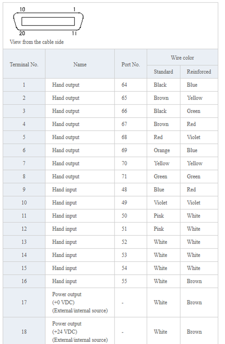
For this cable, terminal #1 is paired with terminal #11, #2 is paired with #12, and so on (The cable has 20 wires total, the pairs are split from 1-10 and 11-20).

This is the Mini IO diagram for RC8 in the manuals. The pinout diagram looks slightly different then the previous one, simply because it has a larger amount of wires to show. You can identify the twisted pairs in this diagram by using the side to side signals listed together.

Next Steps:
- How to access and reference these signals in the robot controller.
This is determined by the port number next to the signal you are looking at.

You can monitor these signals live from the TP -> I/O Screen by looking for corresponding port #.

You can access these signals directly within your programs by port #

You can also define them in your header file


Related Links:
Was this article helpful?
That’s Great!
Thank you for your feedback
Sorry! We couldn't be helpful
Thank you for your feedback
Feedback sent
We appreciate your effort and will try to fix the article